|
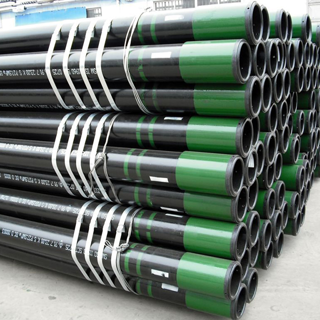


Tubing Sizes
Tubing Sizes | Processed Forms of end finish | ||||||||
Outer Diameter | Wall Thickness | H40 | J55 | L80 | N801 N80Q | C90 T95 | P110 | ||
in | mm | in | mm | ||||||
1.900 | 48.26 | 0.125 | 3.18 | PI | PI | / | / | / | / |
0.145 | 3.68 | PNUI | PNUI | PNUI | PNUI | PNUI | / | ||
0.200 | 5.08 | PU | PU | PU | PU | PU | PU | ||
0.250 | 6.35 | / | / | P | / | P | / | ||
0.300 | 7.62 | / | / | P | / | P | / | ||
2.063 | 52.40 | 0.156 | 3.96 | PI | PI | PI | PI | PI | / |
0.225 | 5.72 | P | P | P | P | P | P | ||
2 3/8 | 60.32 | 0.167 | 4.24 | PU | PN | PN | PN | PN | / |
0.190 | 4.83 | PNU | PNU | PNU | PNU | PNU | PNU | ||
0.254 | 6.45 | / | / | PNU | PNU | PNU | PNU | ||
0.295 | 7.49 | / | / | P | / | P | / | ||
0.336 | 8.53 | / | / | PU | / | PU | / | ||
2 7/8 | 73.02 | 0.217 | 5.51 | PNU | PNU | PNU | PNU | PNU | PNU |
0.276 | 7.01 | / | / | PNU | PNU | PNU | PNU | ||
0.308 | 7.82 | / | / | PNU | PNU | PNU | PNU | ||
0.340 | 8.64 | / | / | PU | / | PU | / | ||
0.392 | 9.96 | / | / | P | / | P | / | ||
0.440 | 11.18 | / | / | P | / | P | / | ||
3 1/2 | 88.90 | 0.216 | 5.49 | PN | PN | PN | PN | PN | / |
0.254 | 6.45 | PNU | PNU | PNU | PNU | PNU | PNU | ||
0.289 | 7.34 | PN | PN | PN | PN | PN | / | ||
0.375 | 9.52 | / | / | PNU | PNU | PNU | PNU | ||
0.430 | 10.92 | / | / | P | / | P | / | ||
0.476 | 12.09 | / | / | P | / | P | / | ||
0.530 | 13.46 | / | / | P | / | P | / | ||
4 | 101.60 | 0.226 | 5.74 | PN | PN | PN | PN | PN | / |
0.262 | 6.65 | PU | PU | PU | PU | PU | / | ||
0.330 | 8.38 | / | / | P | / | P | / | ||
0.415 | 10.54 | / | / | P | / | P | / | ||
0.500 | 12.70 | / | / | P | / | P | / | ||
0.610 | 15.49 | / | / | P | / | P | / | ||
4 1/2 | 114.30 | 0.271 | 6.88 | PNU | PNU | PNU | PNU | PNU | / |
0.337 | 8.56 | / | / | P | / | P | / | ||
0.380 | 9.65 | / | / | P | / | P | / | ||
0.430 | 10.92 | / | / | P | / | P | / | ||
0.500 | 12.70 | / | / | P | / | P | / | ||
0.560 | 14.22 | / | / | P | / | P | / | ||
0.630 | 16.00 | / | / | P | / | P | / | ||
Note: P—plain-end;N—non-upset, with threaded and coupled;U—external-upset, with threaded and coupled;I—whole joint.
Casing Sizes:
Casing Sizes | Processed Forms of end finish | ||||||||||
Outer Diameter | Wall Thickness | H40 | J55 K55 | M65 | L80 | N801 N80Q | C90 T95 | P110 | Q125 | ||
in | mm | in | mm | ||||||||
4 1/2 | 114.30 | 0.205 | 5.21 | PS | PS | PS | / | / | / | / | / |
0.224 | 5.69 | / | PSB | PSB | / | / | / | / | |||
0.250 | 6.35 | / | PSLB | PLB | PLB | PLB | P | PLB | / | ||
0.290 | 7.37 | / | / | PLB | PLB | PLB | P | PLB | / | ||
0.337 | 8.56 | / | / | / | / | / | / | PLB | PLB | ||
5 | 127.00 | 0.220 | 5.59 | / | PS | PS | / | / | / | / | / |
0.253 | 6.43 | / | PSLB | PSLB | / | / | / | / | / | ||
0.296 | 7.52 | / | PSLB | PLB | PLB | PLB | PLB | PLB | / | ||
0.362 | 9.19 | / | / | PLB | PLB | PLB | PLB | PLB | PLB | ||
0.437 | 11.10 | / | / | PLB | PLB | PLB | PLB | PLB | PLB | ||
0.478 | 12.14 | / | / | / | PLB | PLB | PLB | PLB | PLB | ||
0.500 | 12.70 | / | / | / | PLB | PLB | PLB | PLB | PLB | ||
5 1/2 | 139.70 | 0.244 | 6.20 | PS | PS | PS | / | / | / | / | / |
0.275 | 6.98 | / | PSLB | PSLB | / | / | / | / | / | ||
0.304 | 7.72 | / | PSLB | PLB | PLB | PLB | PLB | PLB | / | ||
0.361 | 9.17 | / | / | PLB | PLB | PLB | PLB | PLB | / | ||
0.415 | 10.51 | / | / | PLB | PLB | PLB | PLB | PLB | PLB | ||
0.500 | 12.70 | / | / | / | / | / | P | / | / | ||
0.562 | 14.27 | / | / | / | / | / | P | / | / | ||
0.625 | 15.88 | / | / | / | / | / | P | / | / | ||
0.687 | 17.45 | / | / | / | / | / | P | / | / | ||
0.750 | 19.05 | / | / | / | / | / | P | / | / | ||
0.812 | 20.62 | / | / | / | / | / | P | / | / | ||
0.875 | 22.22 | / | / | / | / | / | P | / | / | ||
6 5/8 | 168.28 | 0.288 | 7.32 | PS | PSLB | PSLB | / | / | / | / | / |
0.352 | 8.94 | / | PSLB | PLB | PLB | PLB | PLB | PLB | / | ||
0.417 | 10.59 | / | / | PLB | PLB | PLB | PLB | PLB | / | ||
0.475 | 12.06 | / | / | / | PLB | PLB | PLB | PLB | PLB | ||
7 | 177.80 | 0.231 | 5.87 | PS | / | / | / | / | / | / | / |
0.272 | 6.91 | PS | PS | PS | / | / | / | / | / | ||
0.317 | 8.05 | / | PSLB | PLB | PLB | PLB | PLB | / | / | ||
0.362 | 9.19 | / | PSLB | PLB | PLB | PLB | PLB | PLB | / | ||
0.408 | 10.36 | / | / | PLB | PLB | PLB | PLB | PLB | / | ||
0.453 | 11.51 | / | / | PLB | PLB | PLB | PLB | PLB | / | ||
0.498 | 12.65 | / | / | / | PLB | PLB | PLB | PLB | PLB | ||
0.540 | 13.72 | / | / | / | PLB | PLB | PLB | PLB | PLB | ||
0.625 | 15.88 | / | / | / | / | / | P | / | / | ||
0.687 | 17.45 | / | / | / | / | / | P | / | / | ||
0.750 | 19.05 | / | / | / | / | / | P | / | / | ||
0.812 | 20.62 | / | / | / | / | / | P | / | / | ||
0.875 | 22.22 | / | / | / | / | / | P | / | / | ||
7 5/8 | 193.68 | 0.300 | 7.62 | PS | / | / | / | / | / | / | / |
0.328 | 8.33 | / | PSLB | PSLB | PLB | PLB | PLB | / | / | ||
0.375 | 9.52 | / | / | PLB | PLB | PLB | PLB | PLB | / | ||
0.430 | 10.92 | / | / | PLB | PLB | PLB | PLB | PLB | / | ||
0.500 | 12.70 | / | / | / | PLB | PLB | PLB | PLB | PLB | ||
0.562 | 14.27 | / | / | / | PLB | PLB | PLB | PLB | PLB | ||
0.595 | 15.11 | / | / | / | PLB | PLB | PLB | PLB | PLB | ||
0.625 | 15.88 | / | / | / | PLB | PLB | PLB | PLB | PLB | ||
0.687 | 17.45 | / | / | / | / | / | P | / | / | ||
0.750 | 19.05 | / | / | / | / | / | P | / | / | ||
7 3/4 | 198.85 | 0.595 | 15.11 | / | / | / | P | P | P | P | P |
Casing Sizes | Processed Forms of end finish | ||||||||||
Outer Diameter | Wall Thickness | H40 | J55 K55 | M65 | L80 | N801 N80Q | C90 T95 | P110 | Q125 | ||
in | mm | in | mm | ||||||||
8 5/8 | 219.08 | 0.264 | 6.71 | / | PS | PS | / | / | / | / | / |
0.304 | 7.72 | PS | / | PS | / | / | / | / | / | ||
0.352 | 8.94 | PS | PSLB | PSLB | / | / | / | / | / | ||
0.400 | 10.16 | / | PSLB | PSLB | PLB | PLB | PLB | / | / | ||
0.450 | 11.43 | / | / | PLB | PLB | PLB | PLB | PLB | / | ||
0.500 | 12.70 | / | / | / | PLB | PLB | PLB | PLB | / | ||
0.557 | 14.15 | / | / | / | PLB | PLB | PLB | PLB | PLB | ||
9 5/8 | 244.48 | 0.312 | 7.92 | PS | / | / | / | / | / | / | / |
0.352 | 8.94 | PS | PSLB | PSLB | / | / | / | / | / | ||
0.395 | 10.03 | / | PSLB | PSLB | PLB | PLB | PLB | / | / | ||
0.435 | 11.05 | / | / | PLB | PLB | PLB | PLB | PLB | / | ||
0.472 | 11.99 | / | / | PLB | PLB | PLB | PLB | PLB | PLB | ||
0.545 | 13.84 | / | / | / | PLB | PLB | PLB | PLB | PLB | ||
0.595 | 15.11 | / | / | / | PLB | PLB | PLB | PLB | PLB | ||
0.609 | 15.47 | / | / | / | / | / | P | / | / | ||
0.672 | 17.07 | / | / | / | / | / | P | / | / | ||
0.734 | 18.64 | / | / | / | / | / | P | / | / | ||
0.797 | 20.24 | / | / | / | / | / | P | / | / | ||
Note:P—plain-end;S—short round thread;L—long round thread;B—buttress thread。
Other size pipes can also be provided after consulting with customers.